LIST p=16F627 ;tell assembler what chip we are using
include "P16F627.inc" ;include the defaults for the chip
__config 0x3D18 ;sets the configuration settings (oscillator type etc.)
; Filename: IOExample2.asm
; IO via interrupts
; Note: there are internal and external interrupts. Internal interrupts are generally
; caused by an internal timer. External interrupts occur when a certain pin changes state
; (either low to high or high to low).
; We deal with external interrupts in this example.
; External interrupts come from either:
; - pin B0 (that is, a change of state in B0 causes an interrupt)
; - pin B4 thru B7 (that is, a change of state on any of B4,B5,B6,B7 causes an interrupt. You must
check each pin to determine which pin caused the interrupt)
The INTCON register:
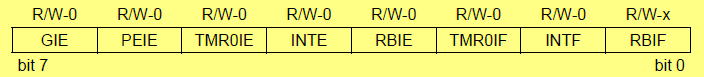
; There is a register called the at 0x0B. Bit 7 of INTCON is called the GIE
; (Global Interrupt Enable). bsf INTCON,GIE enables interrupts. Without this bit set,
; no interrupts will occur.
; Next, we have pairs of bits to consider:
; TMR0IE/TMR0IF
; INTE/INTF
; RBIE/RBIF
;
;
; We will consider the pair INTE/INTF. INTE is the Enable bit for interrupts on pin B0. If you want your program
; to respond to state changes on pin B0, you need to set INTE (this is , of course, assuming you have already enabled
; the GIE pin. ITNF is the INT Flag! When this is set to 1, it indicates that an interrupt on pin B0 has occurred.
; So in the above pairing, the first bit ENABLES a specific interrupt, the second bit (the flag bit) indicates that
; an interrupt of that type has occurred.
; NOTE: if we are looking to execute an interrupt on B0, we can specify if the interrupt occurs on a high-to-low
; transition or a low-to-high transition. We do not have this flexibility on the RBIE/RBIF interrupts. In that case,
; an interrupt occurs on ANY transition and we would need to poll to determine which pin caused the interrupt.
;
;
; Again, for this example, we demonstrate an interrupt on pin B0
;
;
; Next, we must inform the PIC if the interrupt should occur on the rising edge or the falling edge.
; There is a register called the OPTION register (address 0x81.....second bank!!) that
; has a bit called INTEDG (bit 6). Setting to 1 causes interrupt to be processed on the
; rising edge.
;
; When an interrupt occurs, bit 1 in the INTCON register (INTF) is set to 1. While
; it is 1, no other interrupts will be processed. YOU (the programmer!) must reset
; it to 0 (zero).
;
; We'll put an LED on B7 and initially have it off.
; We'll pulse B0, an interrupt, and change the state of the LED
;un-comment the following two lines if using 16f627 or 16f628
org 0x00
goto main
org 0x04
goto isr
main
movlw 0x07
movwf CMCON ;turn comparators off (make it like a 16F84)
; get ready for interrupts
bsf INTCON, GIE ;enable interrupts
bsf INTCON,INTE ;B0 is the interrupt line
; set b port for output
bsf STATUS,RP0 ;goto bank 1
bsf 0x81,INTEDG ;rising edge interrupts
movlw 0x01 ; B0 is an interrupt? Indicate it as input!!!
movwf TRISB ; portb is output
bcf STATUS,RP0 ;go back to bank 0
;start with led on
movlw 0xff
movwf PORTB
cycle
goto cycle ; loop here and wait for interrupt
isr
comf PORTB,f
bcf INTCON,INTF ; the most important line in the program!
retfie
end